Introduction
CAN Bus (Controller Area Network) is widely used in automotive electronics, industrial control systems, robotics, and embedded development. Engineers often need tools to monitor CAN messages, debug communication, and develop CAN-based devices. However, professional CAN analyzers can be expensive.
The HPM5321 PCAN DIY project provides a low-cost and open-source solution that allows developers and makers to build their own USB-to-CAN analyzer tool. This project is based on the HPM5321 microcontroller and can function as a CAN debugging tool, CAN data monitor, and CAN communication interface.
For embedded engineers, automotive developers, and DIY electronics enthusiasts, this is a very practical hardware project.
What Is HPM5321 PCAN?
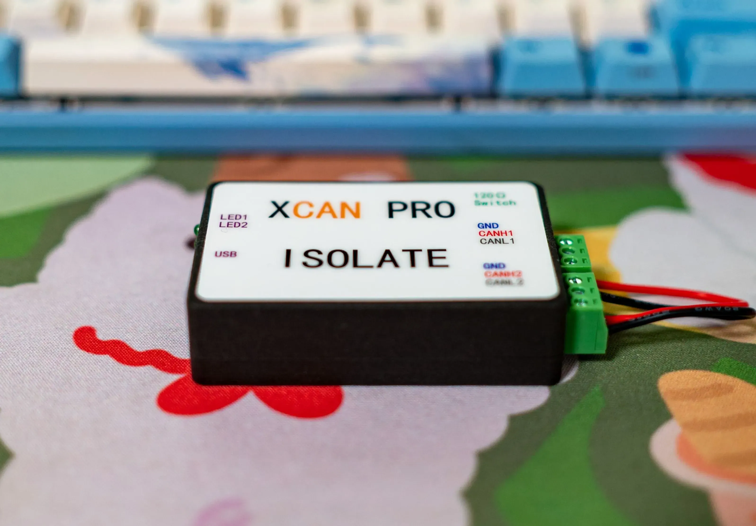
HPM5321 PCAN is an open-source hardware project that implements a USB to CAN interface. It allows a computer to communicate with CAN bus devices through USB, similar to commercial PCAN or USB-CAN analyzers.
This DIY device can be used for:
- CAN bus debugging
- Automotive ECU communication
- Industrial CAN network testing
- Robot control systems
- Embedded system development
- CAN protocol learning and education
In simple terms, it turns your computer into a CAN bus debugging and monitoring platform.
Key Features
The HPM5321 PCAN DIY project includes several important features:
- USB to CAN interface
- Supports CAN bus communication and monitoring
- Based on HPM5321 high-performance microcontroller
- Compact hardware design
- Suitable for automotive and industrial CAN applications
- Open-source hardware and firmware
- Compatible with CAN debugging software
- Low-cost alternative to commercial CAN analyzers
Compared with expensive commercial CAN tools, this DIY project is much more affordable while still being powerful enough for development and debugging.
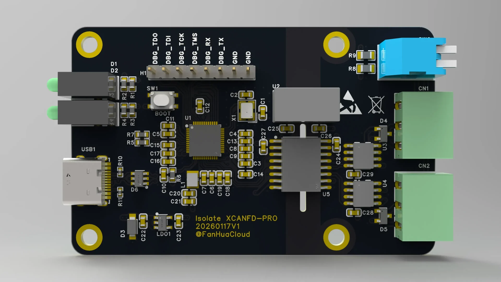
Hardware Overview
The core of this project is the HPM5321 microcontroller, which is designed for high-performance embedded applications and supports CAN communication.
Typical hardware components in this project include:
- HPM5321 microcontroller
- CAN transceiver
- USB interface
- Power management circuit
- Status LEDs
- CAN interface connector
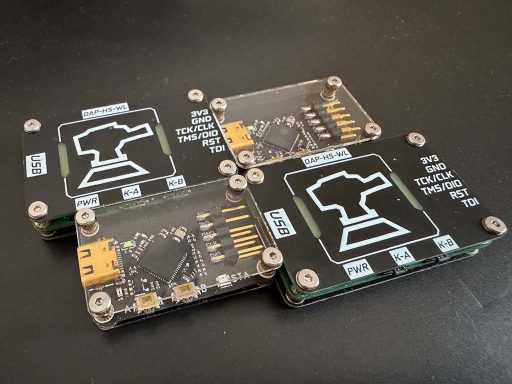
- Programming/debug interface
The hardware design is compact and suitable for DIY assembly.
What Can You Do With a USB-to-CAN Tool?
If you are new to CAN bus, here are some common use cases:
1. Automotive Development
Modern cars use CAN bus to communicate between ECUs (Engine Control Unit, Battery Management System, Dashboard, etc.). With a USB-to-CAN tool, you can:
- Read CAN messages
- Send CAN commands
- Debug ECU communication
- Analyze vehicle data
2. Industrial Control Systems
Many industrial devices use CAN bus for reliable communication. Engineers use CAN analyzers to:
- Monitor device communication
- Debug communication errors
- Test CAN network stability
3. Robotics Projects
Robots often use CAN bus for motor control and sensor communication. A USB-to-CAN tool helps developers test and debug robot communication systems.
4. Embedded System Development
When developing CAN-enabled embedded devices, engineers need to:
- Test CAN protocol implementation
- Send and receive CAN frames
- Perform communication stress testing
- Log CAN data
This DIY PCAN device can handle all of these tasks.
Why Build a DIY CAN Analyzer?
You might ask: why not just buy a commercial CAN analyzer?
Here are some reasons engineers choose DIY:
| DIY CAN Tool | Commercial CAN Tool |
|---|---|
| Low cost | Expensive |
| Open-source | Closed system |
| Can modify firmware | Cannot modify |
| Learn hardware design | Only use device |
| Customizable | Fixed functions |
If you are an embedded engineer, student, or maker, building your own CAN tool is a great learning project.
How to Build the HPM5321 PCAN
According to the open-source project, the general DIY process is:
Step 1 – Download Project Files
Download the hardware design files, PCB files, and firmware from the project page.
Step 2 – Order PCB
Upload the PCB files to a PCB manufacturer and order the board.
Step 3 – Purchase Components
Buy the required components such as:
- HPM5321 MCU
- CAN transceiver
- USB connector
- Crystal oscillator
- Resistors and capacitors
- LEDs
- Connectors
Step 4 – Assemble the PCB
Solder all components onto the PCB.
Step 5 – Flash Firmware
Use a debugger to flash the firmware into the HPM5321 microcontroller.
Step 6 – Connect to PC
After flashing firmware, connect the device to your computer via USB and use CAN software tools to start testing.
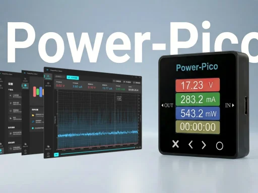
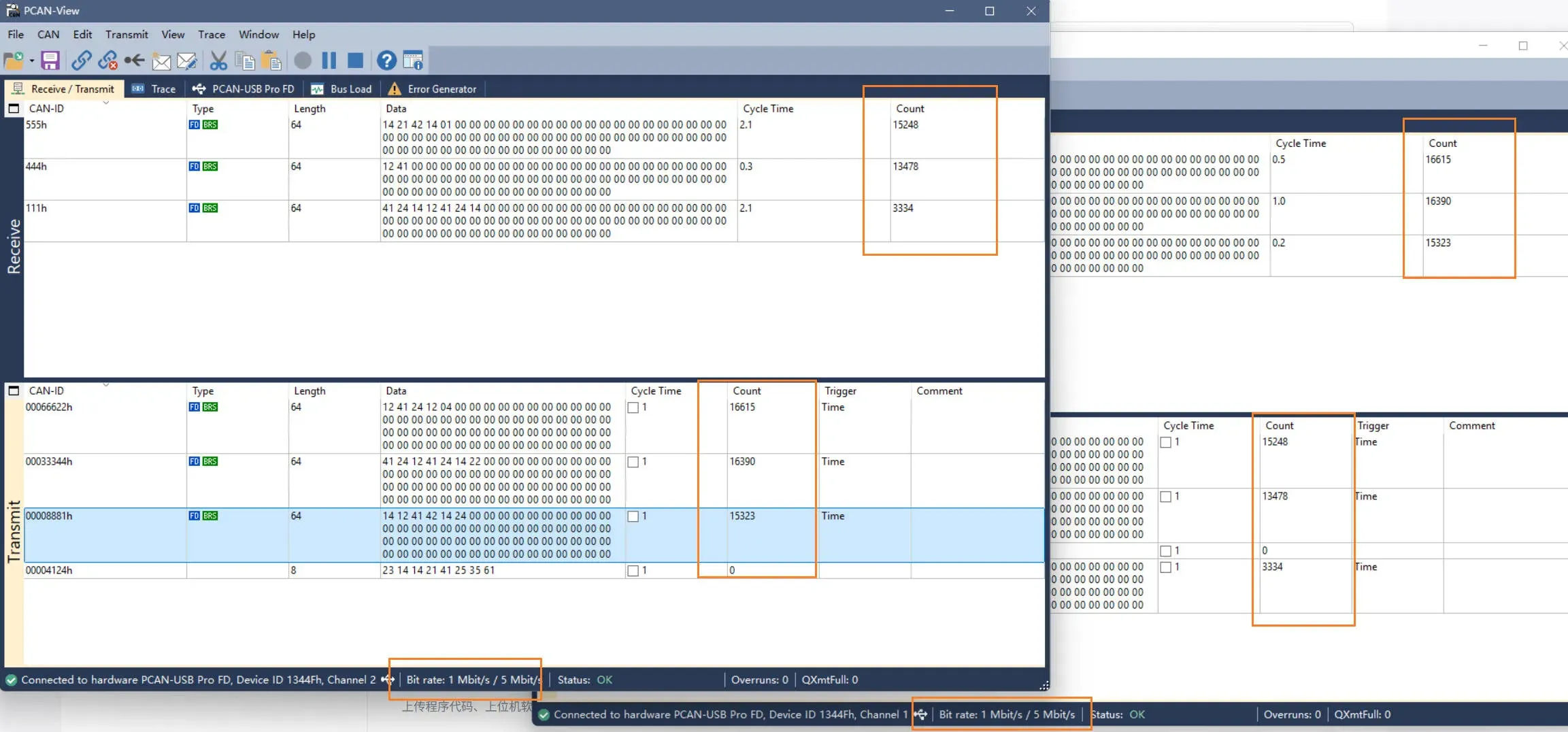
Software and PC Tools
After building the hardware, you can use CAN software on your computer to:
- Monitor CAN messages
- Send CAN frames
- Record CAN data
- Analyze CAN communication
- Debug CAN devices
Many CAN debugging tools support USB-CAN interfaces, making this DIY device very practical.
Who Is This Project For?
This DIY project is ideal for:
- Embedded engineers
- Automotive electronics engineers
- Industrial control engineers
- Robotics developers
- Electronics students
- DIY hardware enthusiasts
- Open-source hardware developers
If your work involves CAN bus, this project is very useful.
Final Thoughts
The HPM5321 PCAN DIY project is a practical and educational open-source hardware project. It allows developers to build their own USB-to-CAN analyzer, which can be used for automotive development, industrial control, robotics, and embedded systems.
Compared with commercial CAN tools, this DIY solution offers:
- Lower cost
- Open-source design
- Custom firmware capability
- Learning opportunity for hardware and embedded development
For engineers and makers who want to understand CAN bus systems or build their own development tools, this is a very worthwhile DIY project.
Original Project Source
This DIY project is based on an open-source hardware project published on OSHWhub.
If you want to view the original design files, schematics, and firmware resources, you can visit the original project page below:
Original Project Link:
HPM5321 PCAN DIY Project – OSHWhub