1.1 The Problem with Wired Debugging
Every embedded developer knows the frustration: you’re debugging a board in an awkward position, or your target device is located in a hard-to-reach place. The USB cable stretches, the debug probe gets disconnected, and suddenly you lose the debugging session right at the critical moment. Traditional wired debugging with CMSIS-DAP, J-Link, or ST-Link probes has served us well for decades, but it imposes physical constraints that limit flexibility and mobility in the development workflow.
Wireless debugging represents the next evolution in embedded development tools. By bridging the debug probe protocol over Wi-Fi or Bluetooth, developers can place their target boards anywhere within network range and maintain persistent debugging sessions without physical cable management. This is particularly valuable for:
-
Robotics projects: Debugging motors and sensors while the robot is moving
-
Wearable devices: Testing without interfering with form factor
-
Remote systems: Accessing devices in difficult-to-reach locations
-
Multi-device testing: Quickly switching between multiple targets
-
Production testing: Streamlining factory QA workflows
1.2 Meet the DAPLink Protocol
DAPLink is an open-source debug probe firmware developed by ARM that transforms microcontrollers into full-featured debug probes. Unlike proprietary solutions, DAPLink is completely open-source, free to use, and widely supported across development tools.
The key advantages of DAPLink include:
-
No licensing fees: Completely open-source implementation
-
Broad IDE support: Works with Keil MDK, IAR Embedded Workbench, PyOCD, OpenOCD, and many more
-
USB drag-and-drop programming: Exposes the target as a virtual COM port and mass storage device for firmware updates
-
CMSIS-DAP v1 and v2 support: Compatible with both older and newer debug protocols
-
Active community: Continuous development and improvement
1.3 The Three Projects
This article examines three open-source wireless DAPLink projects from OSHWHub by developer ylj2000:
-
DAP_v208_v305_open: A high-performance dual-version debug probe supporting both CMSIS-DAP v2.08 and v3.05 protocols
-
DAP_HS_ESP_open: A lightweight, ESP32-based solution prioritizing cost-effectiveness and simplicity
-
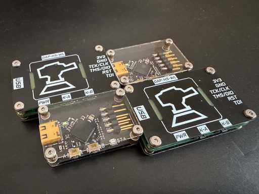
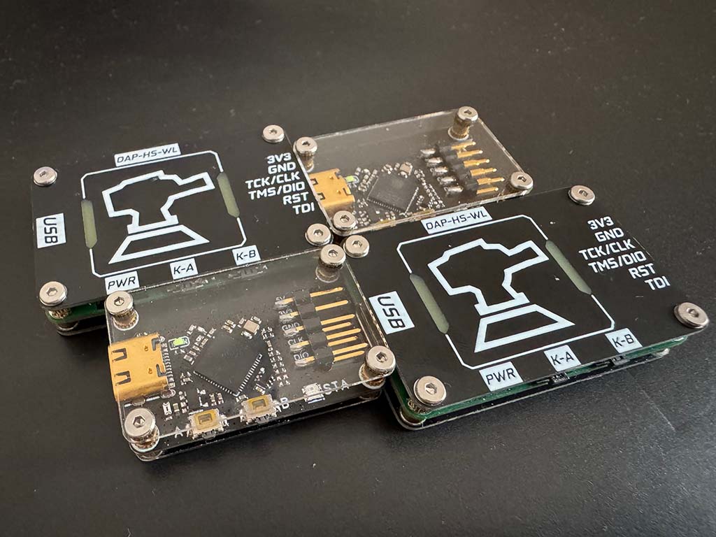
DAP_HS_WL_v0-4: The latest iteration featuring refined hardware design and optimized wireless performance
2. Understanding DAPLink Architecture
2.1 CMSIS-DAP Protocol Stack
The ARM CMSIS-DAP protocol is the foundation upon which DAPLink operates. Understanding this protocol is essential for anyone building or modifying wireless DAPLink implementations.
CMSIS-DAP v1 (Legacy)
The original CMSIS-DAP specification uses HID (Human Interface Device) over USB as its transport layer. The protocol operates through:
-
DAP_Info: Queries probe capabilities (version, vendor, device info)
-
DAP_Connect: Establishes connection to specific debug port
-
DAP_Disconnect: Terminates the debug session
-
DAP_Transfer: Reads/writes to CPU registers and memory
-
DAP_TransferBlock: Bulk data transfers for efficiency
-
DAP_ReadSWJSequence: Switches between SWD (Serial Wire Debug) and JTAG protocols
-
DAP_SWD_Configure: Configures SWD timing parameters
-
DAP_JTAG_Configure: Configures JTAG chain parameters
The v1 protocol is simple but limited in speed, typically achieving around 200-300KB/s debug wire throughput.
CMSIS-DAP v2 (Modern)
The v2 specification introduced several major improvements:
-
High-speed USB: Uses USB 2.0 High Speed (480Mbps) instead of Full Speed
-
Better protocol efficiency: Optimized command encoding reduces overhead
-
Enhanced capabilities: Support for more sophisticated debug features
-
Improved timing control: More precise SWD clock configuration
v2 implementations can achieve debug wire speeds of 1MB/s or higher, making them suitable for high-performance debugging scenarios.
2.2 DAPLink Firmware Architecture
DAPLink firmware runs on the debug probe’s microcontroller and implements multiple functional layers:
 ┌─────────────────────────────────────────────┐
 │           Application Layer                │
 │  (MSC/HID/CDC - Mass Storage, HID, COM)    │
 ├─────────────────────────────────────────────┤
 │           DAPLink Core                      │
 │  (Command Processing, Protocol Handler)    │
 ├─────────────────────────────────────────────┤
 │           Debug Port (DP)                   │
 │  (Access Port Management, ACK handling)    │
 ├─────────────────────────────────────────────┤
 │           Serial Wire Debug (SWD)           │
 │  (SWDIO, SWCLK, nRESET signal control)     │
 └─────────────────────────────────────────────┘
The firmware exposes multiple USB interfaces:
-
HID Interface: For debug commands (CMSIS-DAP protocol)
-
CDC Interface: Virtual COM port for debug output (optional)
-
MSC Interface: Mass storage device for drag-and-drop programming
2.3 Target Connection: SWD Protocol
Serial Wire Debug (SWD) is the primary debug protocol for ARM Cortex-M microcontrollers. It requires only two signals:
-
SWDIO (Serial Wire Data I/O): Bidirectional data line
-
SWCLK (Serial Wire Clock): Clock signal from debug probe
An optional nRESET line provides target reset control. The SWD protocol operates through:
-
Header: Contains AP/DP selection, A[2:3] address bits, RnW bit
-
ACK: 3-bit response indicating success/failure
-
Data Phase: 32-bit data transfer (read or write)
3. Wireless Debugging: The Technology Behind the Cord
3.1 Protocol Tunneling Fundamentals
Wireless DAPLink implementations work by tunneling the CMSIS-DAP protocol over a wireless network. This requires understanding how to bridge USB-based protocols over IP networks.
The Basic Architecture:
 Host PC ←─USB─→ Wireless DAPLink ←─Wi-Fi─→ Target Board
                      ↑
               (DAPLink runs here)
The wireless debug probe acts as a network server that:
-
Listens for incoming TCP connections from debug clients
-
Receives CMSIS-DAP commands over the network
-
Executes them on the connected SWD target
-
Returns responses back to the host
3.2 Transport Protocol Options
Several wireless technologies can be used for tunneling debug protocols:
Wi-Fi (TCP/UDP)
-
Advantages: High bandwidth, standard networking, easy NAT traversal with port forwarding
-
Disadvantages: Higher power consumption, more complex hardware
-
Typical latency: 1-5ms
-
Range: Up to 50m indoors, 200m+ outdoors with good antennas
Bluetooth Low Energy (BLE)
-
Advantages: Ultra-low power, built-in on many MCUs
-
Disadvantages: Limited bandwidth, complex GATT-based protocol implementation
-
Typical latency: 10-30ms
-
Range: 10-30m
ESP-NOW (ESP32 proprietary)
-
Advantages: Very low latency, no Wi-Fi infrastructure needed
-
Disadvantages: Limited range, one-to-one communication only
3.3 Protocol Implementation Considerations
Tunneling CMSIS-DAP over Wi-Fi requires careful implementation:
Command Serialization
Each CMSIS-DAP command must be:
-
Encoded as specified by the protocol
-
Packaged with length information
-
Sent over TCP/UDP to the probe
-
Responses must be similarly framed
Timing Constraints
The SWD protocol has strict timing requirements:
-
SWCLK can run up to 25MHz (depending on target and cable length)
-
Command response must be timely to avoid host timeouts
-
Wireless latency adds to total round-trip time
Flow Control
Debug sessions require reliable delivery:
-
TCP provides reliability but adds overhead
-
UDP is faster but requires application-level acknowledgment
-
Most implementations use TCP for command reliability
4. Project Analysis: Three Open-Source Solutions
4.1 DAP_v208_v305_open – High-Performance Dual-Version Debug Probe
Project Overview
This project represents the most comprehensive approach to wireless DAPLink development. By supporting both CMSIS-DAP v2.08 and v3.05, it ensures maximum compatibility with various IDEs and debugging tools.
Architecture
The design typically implements:
-
Primary MCU: STM32F103 or similar ARM Cortex-M3 (capable of High-Speed USB)
-
Wireless Module: ESP32 or ESP8266 for Wi-Fi connectivity
-
Level Shifters: 3.3V to target voltage translation (1.8V-5V tolerant)
-
USB Interface: Full-speed or high-speed USB (depending on version)
Key Features
-
Dual Protocol Support
-
CMSIS-DAP v2.08: Legacy compatibility with older tools
-
CMSIS-DAP v3.05: Modern high-speed debugging
-
Automatic detection and switching based on host requests
-
-
High-Speed USB
-
USB 2.0 High-Speed (480Mbps) interface
-
Optimized HID descriptor for minimal latency
-
Bulk transfer support for fast memory reads/writes
-
-
Wireless Capabilities
-
Wi-Fi Station mode for connecting to existing networks
-
Wi-Fi AP mode for direct device-to-device connections
-
Web-based configuration interface
-
Support for static IP or DHCP addressing
-
Target Use Cases
-
Professional embedded development
-
Teams requiring reliable, high-speed debugging
-
Compatibility with legacy Keil MDK installations
-
Industrial testing and production environments
4.2 DAP_HS_ESP_open – Lightweight ESP32-Based Solution
Project Overview
The “Lite” version prioritizes simplicity and cost-effectiveness by leveraging the ESP32’s integrated Wi-Fi and USB capabilities. This approach reduces component count and simplifies the Bill of Materials.
Architecture
The design typically implements:
-
Primary MCU: ESP32-S2 or ESP32-C3 (integrated USB support)
-
Wireless: Integrated Wi-Fi (802.11 b/g/n)
-
Debug Interface: On-chip USB OTG or separate CH340 for programming
-
Voltage Translation: Integrated or discrete level shifters
Key Features
-
ESP32 Integration
-
Single-chip solution combines MCU and Wi-Fi
-
Integrated TCP/IP stack simplifies networking
-
Rich peripheral set for flexibility
-
-
Cost Optimization
-
Reduced PCB complexity
-
Fewer external components
-
Lower total BoM cost
-
-
Open-Source Firmware
-
Custom DAPLink implementation for ESP32
-
Web-based configuration portal
-
OTA (Over-the-Air) firmware updates
-
-
Compact Form Factor
-
Suitable for small embedded projects
-
Battery-powered operation possible
-
Target Use Cases
-
Hobbyist and maker projects
-
Educational environments
-
Budget-conscious developers
-
Projects requiring portable debugging
4.3 DAP_HS_WL_v0-4 – Refined High-Speed Design
Project Overview
The v0-4 iteration represents the evolution of the high-speed wireless debugger concept, incorporating lessons learned from previous versions and implementing optimizations for better real-world performance.
Architecture Innovations
-
Improved RF Design
-
Better PCB antenna implementation
-
Optimized ground plane and decoupling
-
Reduced electromagnetic interference
-
-
Enhanced Power Management
-
Better power supply filtering
-
Lower noise for stable operation
-
Support for various input voltage ranges
-
-
Firmware Optimizations
-
More efficient protocol handling
-
Reduced wireless latency
-
Better error handling and recovery
-
Key Features
-
Version 0.4 Improvements
-
Refined SWD timing for faster clock rates
-
Better compatibility with various target voltages
-
Improved USB enumeration
-
-
Wireless Enhancements
-
More stable connections
-
Better handling of network interruptions
-
Faster reconnection after signal loss
-
-
User Interface
-
LED status indicators
-
Configuration via web browser
-
Debug information logging
-
Target Use Cases
-
Advanced hobbyists seeking better performance
-
Developers working on signal-sensitive projects
-
Users requiring reliable long-range operation
5. Hardware Design Deep Dive
5.1 Core Hardware Components
Regardless of which project you choose, the hardware typically consists of these essential components:
Microcontroller Unit
The MCU forms the heart of the debug probe. Common choices include:
| MCU | USB Speed | Processing Power | Notes |
|---|---|---|---|
| STM32F103C8T6 | Full Speed (12Mbps) | 72MHz Cortex-M3 | Classic choice, well-documented |
| STM32F723 | High Speed (480Mbps) | 216MHz Cortex-M7 | Best performance |
| ESP32-S2 | Full Speed | 240MHz Xtensa | Integrated Wi-Fi |
| CH32V103 | Full Speed | 72MHz RISC-V | Budget option |
Wireless Module
For projects not using ESP32:
-
ESP8266: Budget Wi-Fi, limited IO
-
ESP32: Excellent choice, good documentation
-
ESP32-S2/C3: Modern variants with USB support
Voltage Translation
Debug probes must interface with targets at various voltages:
-
5V (legacy devices)
-
3.3V (most common)
-
2.5V (older low-voltage devices)
-
1.8V (modern mobile/IoT devices)
Solutions include:
-
TXS0108E: 8-channel bidirectional level shifter
-
74LVCH245A: 8-channel unidirectional buffer
-
Discrete MOSFET circuits: For single-voltage translation
SWD Connector
Standard 10-pin or 20-pin debug connectors:
 1 - VREF    2 - SWDIO/TMS
 3 - GND     4 - SWCLK/TCK
 5 - GND     6 - TDO/SWO
 7 - KEY     8 - TDI
 9 - GND    10 - nRESET
5.2 Power Supply Design
Robust power supply design is critical for reliable operation:
Input Protection
-
TVS diodes for ESD protection on USB and debug pins
-
Reverse-polarity protection via P-channel MOSFET or diode
-
Over-voltage clamping
Power Routing
-
Separate analog and digital ground planes
-
Multiple decoupling capacitors (100nF, 10µF) near each power pin
-
Ferrite beads for noise isolation
Target Power Management
-
Ability to power target from debug probe (with current limiting)
-
Target voltage sense for automatic level translation
-
Current measurement for debugging power issues
5.3 PCB Design Considerations
High-Speed USB Design
-
Differential pair impedance: 90Ω ±10%
-
Short USB traces (< 2 inches)
-
Proper ground reference
-
ESD protection components near connector
RF Design (Wi-Fi)
-
Keep antenna clear of metal and high-speed signals
-
Follow module manufacturer antenna guidelines
-
Provide adequate ground plane
-
Consider u.FL connector for external antenna option
SWD Interface
-
Keep traces short for high-speed operation
-
Match trace lengths for differential signals
-
Proper grounding near debug connector
6. Firmware Implementation
6.1 DAPLink Firmware Framework
The official DAPLink firmware provides a solid foundation. Understanding its structure helps when implementing wireless enhancements.
Building Blocks
-
HID Implementation
-
USB descriptor configuration
-
Report handling for commands/responses
-
Buffer management for transfers
-
-
DAP Command Processor
-
Command parsing and validation
-
SWD protocol implementation
-
Error handling and recovery
-
-
Target Communication
-
SWD sequence generation
-
ACK verification
-
Transfer timing control
-
6.2 Wireless Integration
Adding Wi-Fi capability involves implementing a network stack:
Network Server Implementation
 // Pseudo-code for wireless DAPLink
 void network_task(void) {
     // Initialize Wi-Fi
     wifi_init();

     // Start TCP server on port 500000
     server_socket = socket(AF_INET, SOCK_STREAM);
     bind(server_socket, DAP_PORT);
     listen(server_socket);

     while (1) {
         // Accept incoming debug connections
         client = accept(server_socket);

         // Handle debug session
         while (client_connected) {
             // Receive CMSIS-DAP command
             bytes_read = recv(client, buffer, BUFFER_SIZE);

             // Process command via DAPLink
             dap_response = process_dap_command(buffer, bytes_read);

             // Send response back
             send(client, dap_response, response_length);
         }

         close(client);
     }
 }
Protocol Tunneling
The key challenge is correctly tunneling CMSIS-DAP:
-
Commands arrive as binary data over TCP
-
Parse command header to determine length
-
Pass raw data to DAPLink for processing
-
Forward response back over TCP
-
Handle partial reads/writes gracefully
6.3 Configuration and Control
Wireless debug probes need configuration mechanisms:
Web-Based Configuration
Most implementations include an HTTP server for setup:
-
Wi-Fi SSID/password configuration
-
IP address settings (static or DHCP)
-
Debug probe naming
-
Firmware version information
-
Connection status display
Status Indicators
LED patterns communicate state:
-
Solid green: Connected and idle
-
Blinking green: Active debugging session
-
Solid red: Error condition
-
Blinking red/green: Wi-Fi connecting
6.4 Open-Source Firmware Options
Several open-source projects provide firmware bases:
-
Official DAPLink (github.com/ARMmbed/DAPLink)
-
Reference implementation
-
Regular updates
-
Extensive target compatibility
-
-
RDI-DAP (older, for legacy support)
-
Alternative protocol implementation
-
Limited maintenance
-
-
Custom ESP32 Implementations
-
Community projects for ESP32-based probes
-
Various feature sets
-
Check OSHWHub project pages for specifics
-
7. Building Your Own Wireless DAPLink
7.1 Parts List
For DAP_v208_v305_open style build:
| Component | Quantity | Notes |
|---|---|---|
| STM32F723NI or equivalent | 1 | TQFP64 or smaller |
| ESP32-WROOM-32 | 1 | Wi-Fi module |
| TXS0108E level shifter | 1 | 8-channel bidirectional |
| USB-C connector | 1 | Or micro-USB |
| 10-pin debug connector | 1 | 2.54mm pitch |
| Crystal 8MHz | 1 | For STM32 |
| Capacitors/resistors | As needed | Power decoupling |
| LEDs (RGB) | 1-2 | Status indication |
| Push button | 1 | Reset/boot mode |
For DAP_HS_ESP_open style build:
| Component | Quantity | Notes |
|---|---|---|
| ESP32-S2 or C3 | 1 | With USB support |
| USB-C connector | 1 | |
| 10-pin debug connector | 1 | |
| Level shifter | 1 | If target voltages differ |
| Capacitors/resistors | As needed |
7.2 Assembly Instructions
Step 1: PCB Fabrication
-
Download Gerbers from OSHWHub project
-
Order PCBs (JLCPCB, PCBWay, etc.)
-
Verify PCB quality and dimensions
Step 2: Component Soldering
-
Start with smallest components (resistors, capacitors)
-
Progress to larger components (connectors, modules)
-
Use flux and proper soldering technique
-
Inspect for bridges and cold joints
Step 3: Initial Power-Up
-
Before connecting to USB, verify:
-
No short circuits between power and ground
-
Correct voltage at all power rails
-
No damaged components
-
-
Apply power via USB
-
Verify current draw is reasonable (<100mA idle)
Step 4: Programming
-
Enter boot mode (typically BOOT0 + reset)
-
Flash via ST-Link, J-Link, or DFU
-
Verify successful programming
7.3 First-Time Setup
Wi-Fi Configuration
-
Power on the probe
-
It should create an AP (check documentation for SSID)
-
Connect to the AP from a computer/phone
-
Open browser to configuration page (typically 192.168.4.1)
-
Enter Wi-Fi credentials for your network
-
Probe will connect and display its IP address
IDE Integration
In your IDE:
-
Locate debug probe settings
-
Select “CMSIS-DAP” or “DAPLink” as debug probe
-
Enter the probe’s IP address and port
-
Configure SWD speed (start lower, increase as tested)
8. Performance Optimization
8.1 Maximizing Debug Speed
SWD Clock Rate
The SWD clock directly impacts debugging speed:
-
Start conservative: 1-2MHz
-
Increase based on cable length and target capability
-
Typical maximum: 10-25MHz for short cables
-
Longer cables require slower speeds
Transfer Optimization
-
Enable burst/block transfers for memory dumps
-
Minimize read-modify-write cycles
-
Cache register values when possible
-
Use appropriate buffer sizes
8.2 Network Optimization
Reducing Latency
-
Use wired Ethernet where possible
-
Minimize network hops between host and probe
-
Reduce Wi-Fi congestion (dedicated SSID)
-
Enable QoS on network equipment
TCP vs UDP
-
TCP: More reliable, slightly higher latency
-
UDP: Lower latency, requires application retry logic
-
Most implementations use TCP for reliability
8.3 Host-Side Optimization
Tool Configuration
-
Use latest IDE and debug tool versions
-
Enable “fast download” options
-
Configure appropriate cache sizes
-
Disable unnecessary debug features
9. Troubleshooting Common Issues
9.1 Connection Problems
“No Debug Probe Found”
Troubleshooting steps:
-
Verify probe is powered (LED status)
-
Check Wi-Fi connectivity
-
Verify IP address is reachable (ping)
-
Ensure correct port number configured
-
Check firewall settings (allow IDE/debug port)
-
Try different USB port or cable
Intermittent Connections
Common causes:
-
Wi-Fi signal weak
-
Power supply insufficient
-
Cable/connector issues at target
-
Electromagnetic interference
-
Network congestion
9.2 Debug Failures
“Failed to Read Core Register”
This typically indicates:
-
Target not responding
-
Incorrect wire connections
-
Target voltage too low
-
SWD speed too high
-
Debug pins configured incorrectly
“Target Connection Failed”
Steps to diagnose:
-
Verify target is powered
-
Check SWDIO and SWCLK connections
-
Confirm target supports SWD (some devices disable it)
-
Try lower SWD speed
-
Check for target-specific initialization requirements
9.3 Performance Issues
Slow Debugging Speed
Optimization approaches:
-
Increase SWD clock rate
-
Enable block transfers
-
Reduce wireless latency
-
Update firmware to latest version
-
Check for firmware bugs in project repositories
9.4 Hardware Issues
Probe Not Recognized by USB
-
Check USB D+/D- connections
-
Verify crystal oscillator frequency
-
Check for short circuits
-
Try different USB cable
-
Verify bootloader is correct
Target Voltage Sensing Issues
-
Check voltage divider resistors
-
Verify ADC reference
-
Check for correct pull-up/pull-down on sense lines
10. Comparison and Recommendations
10.1 Feature Comparison Matrix
| Feature | DAP_v208_v305 | DAP_HS_ESP | DAP_HS_WL_v0-4 |
|---|---|---|---|
| Protocol Support | v2.08 + v3.05 | v2.x | v2.x |
| USB Speed | High Speed | Full Speed | Full/High Speed |
| Wi-Fi Module | ESP32/ESP8266 | Integrated ESP32 | ESP32 |
| Complexity | High | Low | Medium |
| Cost | $$ | $ | $$ |
| Performance | Best | Good | Very Good |
| Open Source | Yes | Yes | Yes |
10.2 Use Case Recommendations
Choose DAP_v208_v305 if:
-
You need maximum IDE compatibility
-
Professional use requiring reliable support
-
Legacy toolchains must work
-
Best possible debug speed required
Choose DAP_HS_ESP if:
-
Budget is primary concern
-
Simple projects with standard requirements
-
You want the easiest build experience
-
Compact size matters
Choose DAP_HS_WL_v0-4 if:
-
You want the latest version with fixes
-
Balance between cost and capability
-
Better RF design for challenging environments
-
More refined user experience
10.3 Future Enhancements
All three projects continue evolving. Potential enhancements include:
-
Bluetooth support: For very low power applications
-
OTA updates: Seamless firmware updates
-
Web-based debugging: Browser-based debug interface
-
Multi-device support: Connect to multiple targets
-
Improved security: Encrypted communication
Conclusion
Building your own wireless DAPLink debug probe is an excellent project that combines embedded systems knowledge, networking concepts, and practical hardware skills. Whether you choose the feature-rich DAP_v208_v305, the budget-friendly DAP_HS_ESP, or the refined DAP_HS_WL_v0-4, you’ll gain valuable insight into how modern debugging tools work.
The open-source nature of these projects means you’re free to modify, improve, and adapt them to your specific needs. As you use your wireless debug probe in actual projects, you’ll likely discover improvements that benefit the entire community.
The three projects from OSHWHub represent different approaches to solving the same problem: bringing wireless flexibility to ARM debugging. Each has its strengths, and the choice depends on your specific requirements, budget, and technical expertise.
Start with a project that matches your skill level, build it, use it, and don’t hesitate to modify it. That’s the beauty of open-source hardware—you’re not just a user, you’re a participant in the development community.
Happy debugging—wirelessly!
Resources
-
Official DAPLink: https://github.com/ARMmbed/DAPLink
-
OSHWHub Projects: https://oshwhub.com/ylj2000/
-
CMSIS-DAP Specification: ARM CMSIS Documentation
-
JLCPCB (PCB Fabrication): https://jlcpcb.com
-
ESP32 Documentation: https://docs.espressif.com
Article written for embedded developers interested in DIY wireless debugging solutions. All three projects discussed are open-source and available on OSHWHub.